The problem statement
Yes, I was one of those people who have an inexplicable apathy towards modern technology invading our lives. This is especially strange because modern tech is what I do. I have since come down from the moral high ground and put an iPhone in my pocket. But back then -- whew, I did not like the things. I did own a smartphone, of course. People did (and still do) expect you to at least be reachable 24/7 on all the socials.
Despite my rebellion towards social pressure, I did (and still od) enjoy most modern comforts. One thing I did regularly was watch TV.
I had a small 27-inch flatscreen
in my student room. I got it from my brother who had moved on to a larger, thinner model years before.
It was really quite alright for how I used it. The 720p screen was not impressive, and you had to squint if you wanted to watch from anywhere else than the awkwardly positioned chair closely in front of it.
In any case, the TV was an oldie, and I did not have a cable subscription. I picked up an Android TV STB (the MiBox 4, if you're interested).
I mainly watched the news, YouTube and public broadcast television. The STB came with a little Bluetooth remote, and that was all fine and dandy. However; I would regularly study and work from my desk and have some background music playing on YouTube from the TV. When I was be done for the day, I would leave the desk. The remote would often stay…
I'm sure you know the feeling. You made tea. You grabbed some biscuits. You settled in with a comfortable blanket and there is no way you would get up out of your chair for anything. You reach for the remote, but alas. No remote.
Smartphone users have it easy; just reach into your pocket and pull out your ad-hoc remote. Great. Problem was that I did not have a smartphone in my pocket, but a brick. A brick you could make phone calls with, sure, but you couldn't do much else with it. Least of all convince your TV to play The Late Show.
The concept
I was really into writing apps at the time. I would regularly pull my smartphone out of the drawer, make a nifty app to solve a problem (or make a problem to make a nifty app) and that would be that. The first idea I had was to write a little application for the dumbphone that would let me interface with it somehow. I remembered some of those old handhelds running Java applications. But as it turned out, I was rocking the king of dumbphones -- the very dumbest. No Java, then. I briefly considered diving into the firmware to expose an interface, but the platform being closed source and the mysterious ways these things are flashed in the factory made me reconsider. The task started to seem impossible. A sad feeling overcame me -- if I couldn't program the thing, how could I use it to do anything…?
After some creative brainstorming, I came up with the following. If you have ever used a dumbphone, you may have noticed that the keypad on some of them will play a little tone when you dial a number. Back in the day, I could play you the Super Mario theme tune just on those twelve keys. Well, those sounds come from a little built-in speaker. That's an interface! Or, well, it could be…
Granted, it is not a very convenient interface. But with enough processing, I should be able to distinguish the sounds these different keys make, and map them to some command for the STB. These we polyphone tones (quite advanced tech indeed), so thing were a little more complicated still. I would have to identify the dominant frequency of each key tone to do the mapping. Furthermore, I would need to get reliable measurements of the tones for calibration and for continuous measurement. A microphone would be too noisy, so I decided to go with a wired interface. As speakers are quite simple analog devices, this involved soldering only two wires to where the phone speaker attached to the motherboard. The change in voltage over these two wires is proportional to the frequency of the tone being played. To measure these continuous changes in voltage, map them to a tone, map the tone to a command and get that command onto a more sensible medium, I went with a small low-power microcontroller breakout board with built-in WiFi. The board was low-powered enough to hook into the phone battery.
The next challenge was to get this command to my STB. As I already mentioned, that device ran Android TV. It was connected to my local network over WiFi, and the ADB is a very flexible interface indeed. It allowed me to emulate key presses over WiFi! Of course, you would have to be connected to the ADB, and running an ADB client on my dumbphone was not going to happen. I decided for a server-client architecture, exposing REST endpoints over HTTP.
Then here we have it; the grand design. The server is pretty straight-forward. The most interesting challenges are at the phone.
A little bit of background…
I will spare the details of shopping around for microcontrollers or the intricacies of how an Analog-Digital Converter (ADC) actually works. Instead, I want to spend a few words on the incredibly beautiful mathematics that let us discover which frequencies a time series is composed of.
Time series data is a collection of measurements made periodically. In this context, we are looking at the periodic measurement of sound. The magical formula which gives us the sounds frequencies is called the Fourier transform. I'm sure you have heard of it.
The hardware
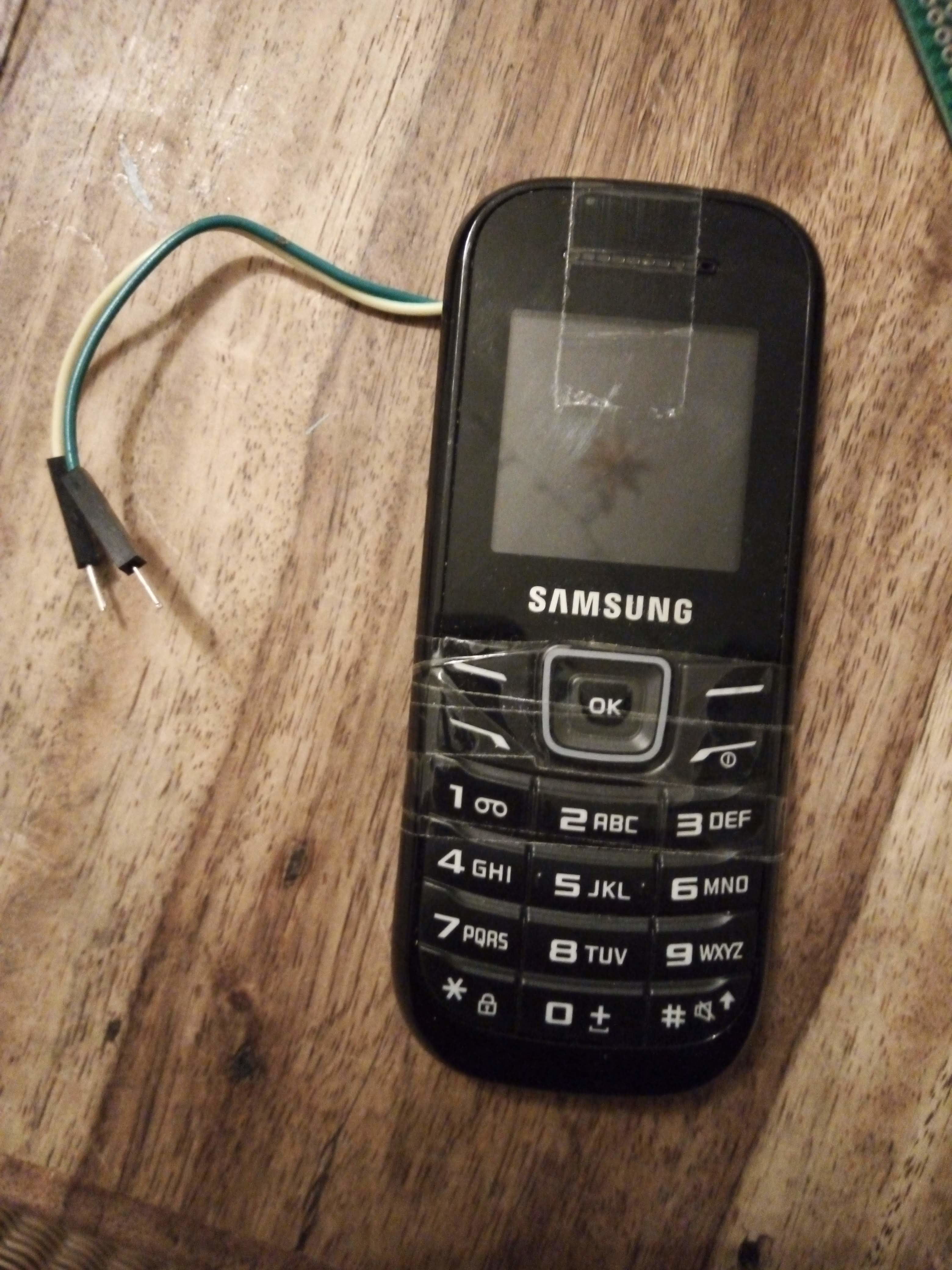
So as I mentioned, the only real interface we have to work with here is the phone's speaker. We don't want to measure the speaker's output using microphones, because microphones are noisy and they pick up a lot more than just the speaker output. Instead, we will be taking voltage measurements over the speaker - which is analogous to its audio output - and it's going to require some soldering.
The speaker is connected by means of two pads on the PCB and two "spring finger" contacts on a tine little speaker. The voltage across those pads directly drives the little speaker, so interfacing with it should be as simple as wiring up two probes to the pads and measuring the voltage across them. This was indeed step one of the project -- getting a voltage reading.
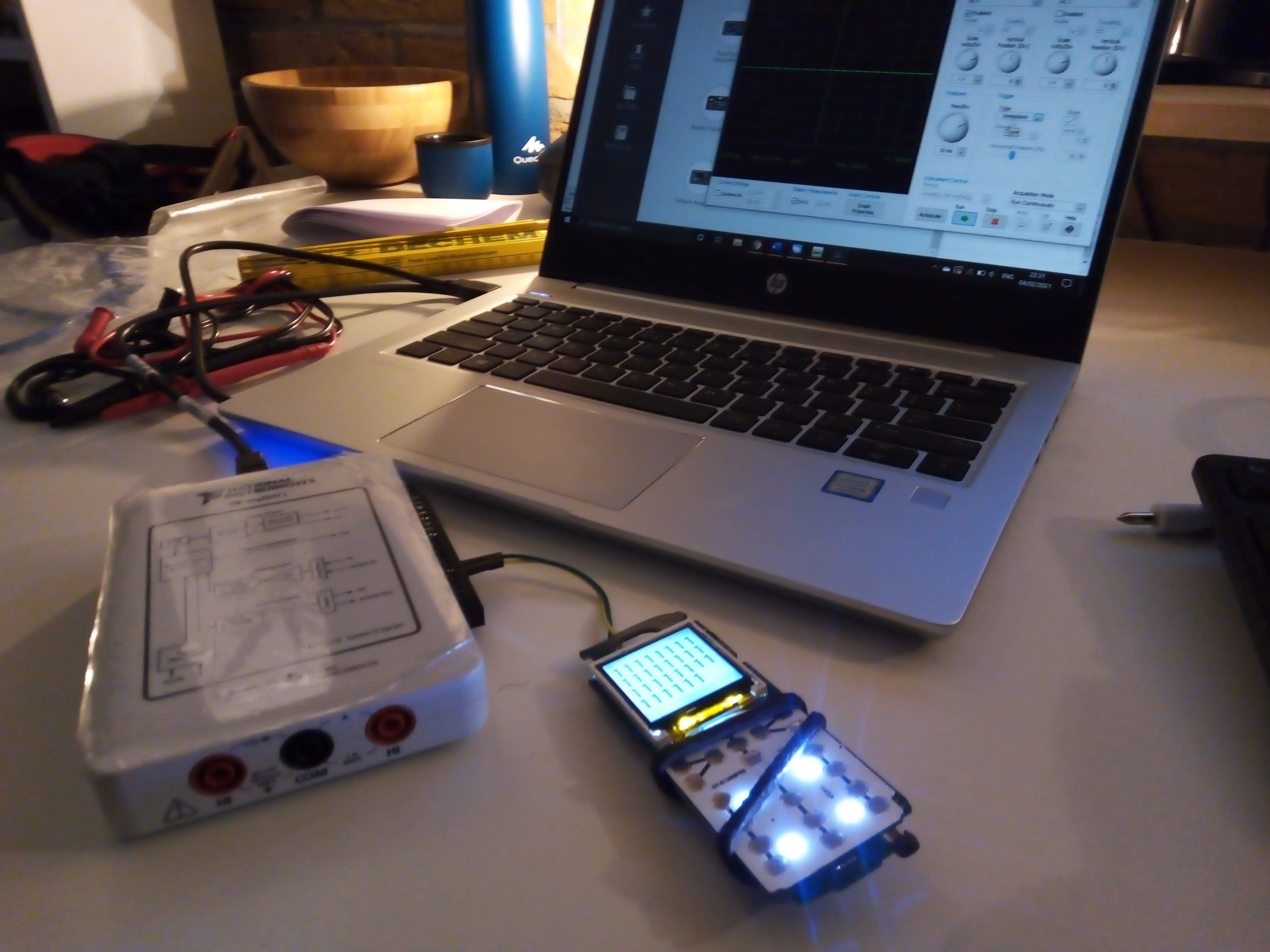
We (yes we - I called in the help of my roommate for this one, he had a nice oscilloscope) hooked up an oscilloscope to the phone to get an idea of how feasable all of this was. Was the signal going to be clean enough? The amplitude great enough?
We took some initial measurements to look at what kind of ranges we could expect at different volume settings of the phone. It turned out that the higher the volume setting, the more useful the signal. Shocker.
As we will discover later, we will end up needing a little more instrumentation to get a usable signal from these pads. That has to do with the fact that the voltages across the speaker oscilate around zero, and the ADCs in the microcontrollers not being capable of measuring negative voltages.
The prototype microcontroller
The prototype was built around a NUCLEO-F303RE. This is an ARM STM32 board running Mbed OS. I had it left over from one of my IoT courses. It was not the best choice (or any choice at all, really), but I did not want to invest anything in this project before getting the implementation a fair bit along.

The board can be programmed in C++. I used the mbed SDK and GCC to cross compile to get that done. This project - like most projects I do - was as much about curiosity and learning as it was about solving my problem. Hence, I went as close to the hardware as possible. The board has some features of particular interest for this project. Most notably, the ADC. This converts analog voltages to a digital value. There are some nice and fancy system functions to interface with it from a program, but that would be the easy way. We came here to explore!
Nearly all memory is shared on this device. This means that the ADC can be configured, instructed and read just by setting and unsetting the right bits in absolute memory from our program! This gives us full control over how we interact with the component - no drivers needed! The memory was quite limited for signal processing though. I only had around 80KB of SRAM to work with.
It is actually quite a nice platform to work with. Unfortunately, this particular board is just too large for my use case. It is great for prototyping, but I eventually had to get something smaller. More on that later. Aditionally it did not have a built-in WiFi interface, which would take money, complexity and physical space to integrate.
The buffer circuit
As I've mentioned, the speaker voltage goes between negative and positve voltage. The amplitude and frequency of this are interesting to us. However, our ADC reads zero for all negative voltages. This means we are clipping -- hard. To solve this issue, we want to lift this signal to the postive voltage region - clamp it - without clipping the peaks.
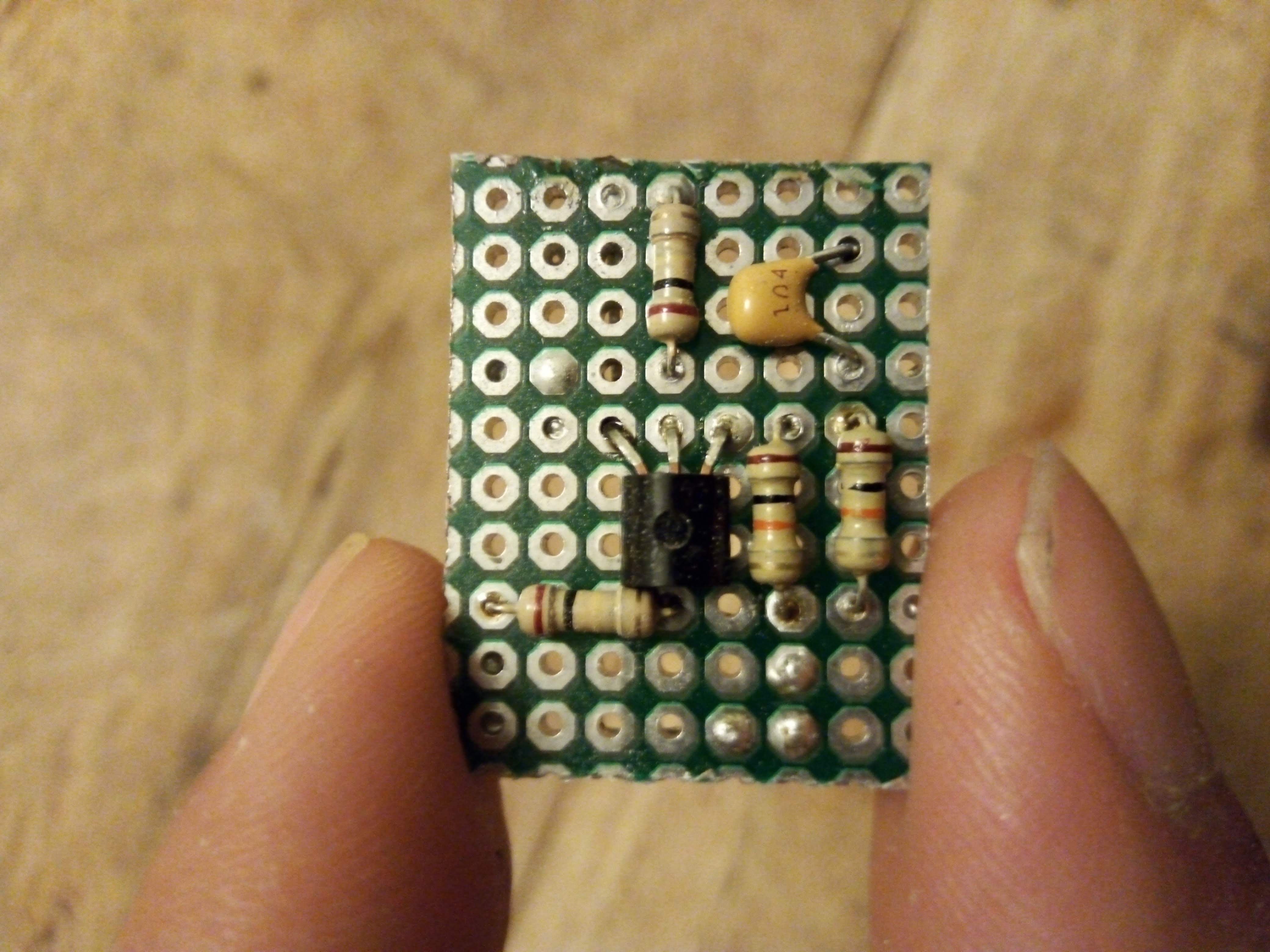
Our buffer circuit handles this for us. It lifts the voltage by a experimentally obtained amount. Of course, we aim to minimize distorting the signal as much as we can. I really have to give credit where credit is due -- Taki, I appreaciate your help with this immensely. Not only for coming up with the design of the circuit, but also for explaining it to me patiently and in painstaking detail.
I did do the PCB layout and soldering of the thing all by myself (credit where credit is due…).
The code
TODO: arguable the most interesting section. Calibrating and configuring the ADC for high performace. Implementing the FFT. Memory management. Tone/key mapping. The WiFi interface.
The production
microcontroller
TODO: The differences in hardware (voltage!) and code.
The server
TODO: describe the NodeJS server, show some code snippets (maybe process invocation of adb commands?) or configuration.
The TV interface
Describe the ADB WiFi interface, the interesting commands, the latency.
The result
TODO: discuss the final product. The fact that this was more work than picking up the remote for three lifetimes. What have I learned?